
Module Overview
34.1 Serial
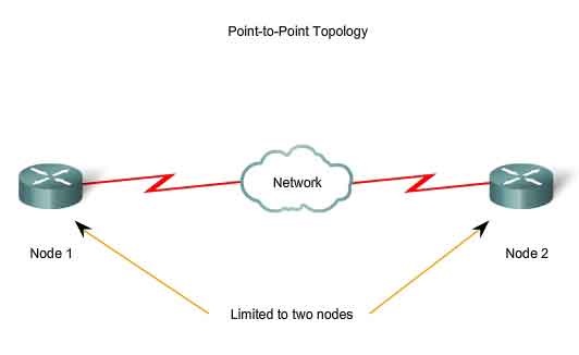
Point-to-Point Links
34.1.1
Introduction to serial communication
34.1.2
Time-division multiplexing
34.1.3
Demarcation point
34.1.4
DTE/DCE
34.1.5 HDLC
encapsulation
34.1.6
Configuring HDLC encapsulation
34.1.7
Troubleshooting a serial interface
34.2 PPP
Authentication
34.2.1 PPP
layered architecture
34.2.2
Establishing a PPP session
34.2.3 PPP
authentication protocols
34.2.4 Password
Authentication Protocol (PAP)
34.2.5 Challenge
Handshake Authentication Protocol (CHAP)
34.2.6 PPP
encapsulation and authentication process
34.3 Configuring
PPP
34.3.1
Introduction to configuring PPP
34.3.2
Configuring PPP
34.3.3
Configuring PPP authentication
34.3.4 Verifying
the serial PPP encapsulation configuration
34.3.5
Troubleshooting the serial encapsulation configuration
Module: Summary
Overview
This module
presents an overview of WAN technologies. It introduces and explains WAN
terminologies such as serial transmission, time division multiplexing (TDM),
demarcation, data terminal equipment (DTE) and data communications equipment
(DCE). The development and use of high-level data link control (HDLC)
encapsulation as well as methods to configure and troubleshoot a serial
interface are presented.
Point-to-Point
Protocol (PPP) is the protocol of choice to implement over a serial WAN
switched connection. It can handle both synchronous and asynchronous
communication and includes error detection. Most importantly it incorporates an
authentication process using either CHAP or PAP. PPP can be used on various
physical media, including twisted pair, fiber optic lines, and satellite
transmission.
The configuration
procedures for PPP, as well as available options and troubleshooting concepts,
are described in this module.
Students
completing this module should be able to:
- Explain serial communication
- Describe and give an example of
TDM
- Identify the demarcation point
in a WAN
- Describe the functions of the
DTE and DCE
- Discuss the development of HDLC
encapsulation
- Use the encapsulation hdlc
command to configure HDLC
- Troubleshoot a serial interface
using the show interface and show controllers commands
- Identify the advantages of
using PPP
- Explain the functions of the
Link Control Protocol (LCP) and the Network Control Protocol (NCP)
components of PPP
- Describe the parts of a PPP
frame
- Identify the three phases of a
PPP session
- Explain the difference between
PAP and CHAP
- List the steps in the PPP
authentication process
- Identify the various PPP
configuration options
- Configure PPP encapsulation
- Configure CHAP and PAP
authentication
- Use show interface to verify
the serial encapsulation
- Troubleshoot any problems with
the PPP configuration using debug PPP
34.1 Serial Point-to-Point Links
34.1.1 Introduction to serial communication
WAN technologies
are based on serial transmission at the physical layer. This means that the
bits of a frame are transmitted one at a time over the physical medium.
The bits that
make up the Layer 2 frame are signaled one at a time by physical layer
processes onto the physical medium. The
signaling methods include Nonreturn to Zero Level (NRZ-L), High Density Binary
3 (HDB3), and Alternative Mark Inversion (AMI). These are examples of physical
layer encoding standards, similar to Manchester encoding for Ethernet. Among
other things, these signaling methods differentiate between one serial
communication method and another. Some of the many different serial
communications standards are as follows:
- RS-232-E
- V.35
- High Speed Serial Interface
(HSSI)
34.1
Serial Point-to-Point Links
34.1.2 Time-division multiplexing
Time-division
multiplexing (TDM) is the transmission of several sources of information using
one common channel, or signal, and then the reconstruction of the original
streams at the remote end.
In the example
shown in Figure , there are three sources of information carried in turn down
the output channel. First, a chunk of information is taken from each input channel.
The size of this chunk may vary, but typically it is either a bit or a byte at
a time. Depending on whether bits or bytes are used, this type of TDM is called
bit-interleaving or byte-interleaving.
Each of the three
input channels has its own capacity. For the output channel to be able to
accommodate all the information from the three inputs, the capacity of the
output channel must be no less than the sum of the inputs.
In TDM, the
output timeslot is always present whether or not the TDM input has any
information to transmit. TDM output can be compared to a train with 32 railroad
cars. Each is owned by a different freight company and every day the train
leaves with the 32 cars attached. If one of the companies has product to send,
the car is loaded. If the company has nothing to send, the car remains empty,
but it is still part of the train.
TDM is a physical
layer concept, it has no regard for the nature of the information that is being
multiplexed onto the output channel. TDM is independent of the Layer 2 protocol
that has been used by the input channels.
One TDM example
is Integrated Services Digital Network (ISDN). ISDN basic rate (BRI) has three
channels consisting of two 64 kbps B-channels (B1 and B2), and a 16 kbps
D-channel. The TDM has nine timeslots, which are repeated.
34.1 Serial Point-to-Point Links
34.1.3 Demarcation point
The demarcation
point, or "demarc" as it is commonly known, is the point in the
network where the responsibility of the service provider or "telco"
ends. In the United States, a telco provides the local loop into the customer
premises and the customer provides the active equipment such as the channel
service unit/data service unit (CSU/DSU) on which the local loop is terminated.
This termination often occurs in a telecommunications closet and the customer
is responsible for maintaining, replacing, or repairing the equipment.
In other
countries around the world, the network terminating unit (NTU) is provided and
managed by the telco. This allows the telco to actively manage and troubleshoot
the local loop with the demarcation point occurring after the NTU. The customer
connects a customer premises equipment (CPE) device, such as a router or frame
relay access device, into the NTU using a V.35 or RS-232 serial interface.
34.1 Serial Point-to-Point Links
34.1.4 DTE/DCE
A serial
connection has a data terminal equipment (DTE) device at one end of the
connection and a data communications equipment (DCE) device at the other end.
The connection between the two DCEs is the WAN service provider transmission
network. The CPE, which is generally a router, is the DTE. Other DTE examples
could be a terminal, computer, printer, or fax machine. The DCE, commonly a
modem or CSU/DSU, is the device used to convert the user data from the DTE into
a form acceptable to the WAN service provider transmission link. This signal is
received at the remote DCE, which decodes the signal back into a sequence of
bits. This sequence is then signaled to the remote DTE.
Many standards
have been developed to allow DTEs to communicate with DCEs. The Electronics
Industry Association (EIA) and the International Telecommunication Union
Telecommunications Standardization Sector (ITU-T) have been most active in the
development of these standards. The ITU-T refers to the DCE as data
circuit-terminating equipment. The EIA refers to the DCE as data communication
equipment.
The DTE/DCE
interface for a particular standard defines the following specifications:
- Mechanical/physical
- Number of pins and connector type
- Electrical
- Defines voltage levels for 0 and 1
- Functional -
Specifies the functions that are performed by assigning meanings to each
of the signaling lines in the interface
- Procedural
- Specifies the sequence of events for transmitting data
If two DTEs must
be connected together, like two computers or two routers in the lab, a special
cable called a null-modem is necessary to eliminate the need for a DCE. For
synchronous connections, where a clock signal is needed, either an external
device or one of the DTEs must generate the clock signal.
The synchronous serial port on
a router is configured as DTE or DCE depending on the attached cable, which is
ordered as either DTE or DCE to match the router configuration. If the port is
configured as DTE, which is the default setting, external clocking is required
from the CSU/DSU or other DCE device.
The cable for the
DTE to DCE connection is a shielded serial transition cable. The router end of
the shielded serial transition cable may be a DB-60 connector, which connects
to the DB-60 port on a serial WAN interface card. The other end of the serial
transition cable is available with the connector appropriate for the standard
that is to be used. The WAN provider or the CSU/DSU usually dictates this cable
type. Cisco devices support the EIA/TIA-232, EIA/TIA-449, V.35, X.21, and
EIA/TIA-530 serial standards.
To support higher
densities in a smaller form factor, Cisco has introduced a Smart Serial cable.
The router interface end of the Smart Serial cable is a 26-pin connector
significantly more compact than the DB-60 connector.
34.1 Serial Point-to-Point Links
34.1.5 HDLC encapsulation
Initially, serial
communications were based on character-oriented protocols. Bit-oriented protocols
were more efficient but they were also proprietary. In 1979, the ISO agreed on
HDLC as a standard bit-oriented data link layer protocol that encapsulates data
on synchronous serial data links. This standardization led to other committees
adopting it and extending the protocol. Since 1981, ITU-T has developed a
series of HDLC derivative protocols. The following examples of derivative
protocols are called link access protocols:
- Link Access Procedure, Balanced
(LAPB) for X.25
- Link Access Procedure on the D
channel (LAPD) for ISDN
- Link Access Procedure for
Modems (LAPM) and PPP for modems
- Link Access Procedure for Frame
Relay (LAPF) for Frame Relay
HDLC uses
synchronous serial transmission providing error-free communication between two
points. HDLC defines a Layer 2 framing structure that allows for flow control
and error control using acknowledgments and a windowing scheme. Each frame has
the same format, whether it is a data frame or a control frame.
Standard HDLC
does not inherently support multiple protocols on a single link, as it does not
have a way to indicate which protocol is being carried. Cisco offers a
proprietary version of HDLC. The Cisco HDLC frame uses a proprietary 'type'
field that acts as a protocol field. This field enables multiple network layer
protocols to share the same serial link. HDLC is the default Layer 2 protocol
for Cisco router serial interfaces.
HDLC defines the
following three types of frames, each with a different control field format:
- Information frames (I-frames)
- Carry the data to be transmitted for the station. There is additional
flow and error control, and data may be piggybacked on an information
frame.
- Supervisory frames (S-frames)
- Provide request/response mechanisms when piggybacking is not used.
- Unnumbered frames (U-frames)
- Provide supplemental link control functions, such as connection setup.
The code field identifies the U-frame type.
The first one or two bits of
the control field serve to identify the frame type. In the control field of an
Information (I) frame, the send-sequence number refers to the number of the
frame to be sent next. The receive-sequence number provides the number of the
frame to be received next. Both sender and receiver maintain send and receive
sequence numbers.
34.1 Serial Point-to-Point Links
34.1.6 Configuring HDLC encapsulation
The default
encapsulation method used by Cisco devices on synchronous serial lines is Cisco
HDLC. If the serial interface is configured with another encapsulation
protocol, and the encapsulation must be changed back to HDLC, enter the
interface configuration mode of the serial interface. Then enter the
encapsulation hdlc command to specify the encapsulation protocol on the
interface.
Cisco HDLC is a
point-to-point protocol that can be used on leased lines between two Cisco
devices. When communicating with a non-Cisco device, synchronous PPP is a more
viable option.
34.1
Serial Point-to-Point Links
34.1.7 Troubleshooting a serial interface
The output of the
show interfaces serial command displays information specific to serial
interfaces. When HDLC is configured, "Encapsulation HDLC" should be
reflected in the output. When PPP is
configured, "Encapsulation PPP" should be seen in the output.
Five possible
problem states can be identified in the interface status line of the show
interfaces serial display:
- Serial x is down, line protocol
is down
- Serial x is up, line protocol
is down
- Serial x is up, line protocol
is up (looped)
- Serial x is up, line protocol
is down (disabled)
- Serial x is administratively
down, line protocol is down
The show
controllers command is another important diagnostic tool when troubleshooting
serial lines. The show controllers output indicates the state of the interface
channels and whether a cable is attached to the interface. In Figure , serial
interface 0/0 has a V.35 DTE cable attached. The command syntax varies,
depending on platform. For serial interfaces on Cisco 7000 series routers, use
the show controllers cbus command.
If the electrical
interface output is shown as UNKNOWN, instead of V.35, EIA/TIA-449, or some
other electrical interface type, an improperly connected cable is the likely
problem. A problem with the internal wiring of the card is also possible. If
the electrical interface is unknown, the corresponding display for the show
interfaces serial <X> command will show that the interface and line
protocol are down.
CAUTION:
Debugging output
is assigned high priority in the CPU process and can render the system unusable.
For this reason, debug commands should only be used to troubleshoot specific
problems or during troubleshooting sessions with Cisco technical support staff.
It is good practice to use debug commands during periods of low network traffic
and when the fewest users are online. Debugging during these periods decreases
the likelihood that increased debug command processing overhead will affect
system use.
34.2 PPP Authentication
34.2.1 PPP layered architecture
PPP uses a
layered architecture. A layered architecture is a logical model, design, or
blueprint that aids in communication between interconnecting layers. The Open
System Interconnection (OSI) model is the layered architecture used in
networking. PPP provides a method for encapsulating multi-protocol datagrams
over a point-to-point link, and uses the data link layer for testing the
connection. Therefore PPP is made up of two sub-protocols:
- Link Control Protocol
- Used for establishing the point-to-point link.
- Network Control Protocol
- Used for configuring the various network layer protocols.
PPP can be configured on the
following types of physical interfaces:
- Asynchronous serial
- Synchronous serial
- High-Speed Serial Interface
(HSSI)
- Integrated Services Digital
Network (ISDN)
PPP uses Link
Control Protocol (LCP) to negotiate and setup control options on the WAN data
link. PPP uses the Network Control Protocol (NCP) component to encapsulate and
negotiate options for multiple network layer protocols. The LCP sits on top of
the physical layer and is used to establish, configure, and test the data-link
connection.
PPP also uses LCP
to automatically agree upon encapsulation format options such as:
- Authentication
- Authentication options require that the calling side of the link enter
information to help ensure the caller has the network administrator's
permission to make the call. Peer routers exchange authentication
messages. Two authentication choices are Password Authentication Protocol
(PAP) and Challenge Handshake Authentication Protocol (CHAP).
- Compression
- Compression options increase the effective throughput on PPP connections
by reducing the amount of data in the frame that must travel across the
link. The protocol decompresses the frame at its destination. Two
compression protocols available in Cisco routers are Stacker and
Predictor.
- Error detection
- Error detection mechanisms with PPP enable a process to identify fault
conditions. The Quality and Magic Number options help ensure a reliable,
loop-free data link.
- Multilink
- Cisco IOS Release 11.1 and later supports multilink PPP. This
alternative provides load balancing over the router interfaces that PPP
uses.
- PPP Callback
- To further enhance security, Cisco IOS Release 11.1 offers callback over
PPP. With this LCP option, a Cisco router can act as a callback client or
as a callback server. The client makes the initial call, requests that it
be called back, and terminates its initial call. The callback router
answers the initial call and makes the return call to the client based on
its configuration statements.
LCP will also do the following:
- Handle varying limits on packet
size
- Detect common misconfiguration
errors
- Terminate the link
- Determine when a link is
functioning properly or when it is failing
PPP permits
multiple network layer protocols to operate on the same communications link.
For every network layer protocol used, a separate Network Control Protocol
(NCP) is provided. For example, Internet Protocol (IP) uses the IP Control
Protocol (IPCP), and Internetwork Packet Exchange (IPX) uses the Novell IPX
Control Protocol (IPXCP). NCPs include functional fields containing
standardized codes to indicate the network layer protocol type that PPP
encapsulates.
The fields of a
PPP frame are as follows:
- Flag
- Indicates the beginning or end of a frame and consists of the binary
sequence 01111110.
- Address
- Consists of the standard broadcast address, which is the binary sequence
11111111. PPP does not assign individual station addresses.
- Control -
1 byte that consists of the binary sequence 00000011, which calls for
transmission of user data in an unsequenced frame. A connectionless link
service similar to that of Logical Link Control (LLC) Type 1 is provided.
- Protocol
- 2 bytes that identify the protocol encapsulated in the data field of the
frame.
- Data
- 0 or more bytes that contain the datagram for the protocol specified in
the protocol field. The end of the data field is found by locating the
closing flag sequence and allowing 2 bytes for the frame check sequence
(FCS) field. The default maximum length of the data field is 1500 bytes.
- FCS
- Normally 16 bits or 2 bytes that refers to the extra characters added to
a frame for error control purposes.
34.2 PPP Authentication
34.2.2 Establishing a PPP session
PPP session
establishment progresses through three phases. These phases are link
establishment, authentication, and the network layer protocol phase. LCP frames are used to accomplish the work of
each of the LCP phases. The following three classes of LCP frames are used in a
PPP session:
- Link-establishment frames are
used to establish and configure a link.
- Link-termination frames are
used to terminate a link.
- Link-maintenance frames are
used to manage and debug a link.
The three PPP session
establishment phases are:
- Link-establishment phase
- In this phase each PPP device sends LCP frames to configure and test the
data link. LCP frames contain a configuration option field that allows
devices to negotiate the use of options such as the maximum transmission
unit (MTU), compression of certain PPP fields, and the link-authentication
protocol. If a configuration option is not included in an LCP packet, the
default value for that configuration option is assumed. Before any network layer packets can be
exchanged, LCP must first open the connection and negotiate the
configuration parameters. This phase is complete when a configuration
acknowledgment frame has been sent and received.
- Authentication phase (optional)
- After the link has been established and the authentication protocol
decided on, the peer may be authenticated. Authentication, if used, takes
place before the network layer protocol phase is entered. As part of this
phase, LCP also allows for an optional link-quality determination test.
The link is tested to determine whether the link quality is good enough to
bring up network layer protocols.
- Network layer protocol phase
- In this phase the PPP devices send NCP packets to choose and configure
one or more network layer protocols, such as IP. Once each of the chosen network layer
protocols has been configured, packets from each network layer protocol
can be sent over the link. If LCP closes the link, it informs the network
layer protocols so that they can take appropriate action. The show
interfaces command reveals the LCP and NCP states under PPP configuration.
The PPP link
remains configured for communications until either of the following:
- LCP or NCP frames close the
link.
- An inactivity timer expires.
- A user intervenes.
34.2 PPP Authentication
34.2.3 PPP authentication protocols
The
authentication phase of a PPP session is optional. After the link has been
established and the authentication protocol chosen, the peer can be
authenticated. If it is used, authentication takes place before the network
layer protocol configuration phase begins.
The
authentication options require that the calling side of the link enter
authentication information. This helps to ensure that the user has the
permission of the network administrator to make the call. Peer routers exchange
authentication messages.
When configuring
PPP authentication, the network administrator can select Password
Authentication Protocol (PAP) or Challenge Handshake Authentication Protocol
(CHAP). In general, CHAP is the
preferred protocol.
34.2
PPP Authentication
34.2.4 Password Authentication Protocol (PAP)
PAP provides a
simple method for a remote node to establish its identity, using a two-way
handshake. After the PPP link
establishment phase is complete, a username/password pair is repeatedly sent by
the remote node across the link until authentication is acknowledged or the
connection is terminated.
PAP is not a
strong authentication protocol. Passwords are sent across the link in clear
text and there is no protection from playback or repeated trial-and-error
attacks. The remote node is in control of the frequency and timing of the login
attempts.
34.2
PPP Authentication
34.2.5 Challenge Handshake Authentication Protocol
(CHAP)
CHAP is used at
the startup of a link and periodically verifies the identity of the remote node
using a three-way handshake. CHAP is performed upon initial link establishment
and is repeated during the time the link is established.
After the PPP link
establishment phase is complete, the local router sends a "challenge"
message to the remote node. The remote
node responds with a value calculated using a one-way hash function, which is
typically Message Digest 5 (MD5). This response is based on the password and
challenge message. The local router
checks the response against its own calculation of the expected hash value. If
the values match, the authentication is acknowledged, otherwise the connection
is immediately terminated.
CHAP provides
protection against playback attack through the use of a variable challenge
value that is unique and unpredictable. Since the challenge is unique and
random, the resulting hash value will also be unique and random. The use of
repeated challenges is intended to limit the time of exposure to any single
attack. The local router or a third-party authentication server is in control
of the frequency and timing of the challenges.
34.2
PPP Authentication
34.2.6 PPP encapsulation and authentication
process
When the
encapsulation ppp command is used, either PAP or CHAP authentication can be
optionally added. If no authentication is specified the PPP session starts
immediately. If authentication is required the process proceeds through the
following steps:
- The method of authentication is
determined.
- The local database or security
server, which has a username and password database, is checked to see if
the given username and password pair matches.
- The process checks the
authentication response sent back from the local database. If it is a
positive response, the PPP session is started. If negative, the session is
terminated.
The Figure and corresponding Figure details the CHAP authentication process.
34.3
Configuring PPP
34.3.1 Introduction to configuring PPP
Configurable
aspects of PPP include methods of authentication, compression, error detection,
and whether or not multilink is supported. The following section describes the
different configuration options for PPP.
Cisco routers that use PPP
encapsulation may include the LCP configuration options described in Figure .
34.3 Configuring PPP
34.3.2 Configuring PPP
The following
example enables PPP encapsulation on serial interface 0/0:
Router#configure
terminal
Router(config)#interface
serial 0/0
Router(config-if)#encapsulation
ppp
Point-to-point
software compression can be configured on serial interfaces that use PPP
encapsulation. Compression is performed in software and might significantly
affect system performance. Compression is not recommended if most of the
traffic consists of compressed files.
To configure
compression over PPP, enter the following commands:
Router(config)#interface
serial 0/0
Router(config-if)#encapsulation
ppp
Router(config-if)#compress
[predictor | stac]
Enter the
following to monitor the data dropped on the link, and avoid frame looping:
Router(config)#interface
serial 0/0
Router(config-if)#encapsulation
ppp
Router(config-if)#ppp
quality percentage
The following
commands perform load balancing across multiple links:
Router(config)#interface
serial 0/0
Router(config-if)#encapsulation
ppp
Router(config-if)#ppp
multilink
34.3 Configuring PPP
34.3.3 Configuring PPP authentication
The procedure
outlined in the table describes how to configure PPP encapsulation and PAP/CHAP
authentication protocols.
Correct
configuration is essential, since PAP and CHAP will use these parameters to
authenticate.
Figure is an example of a two-way PAP authentication
configuration. Both routers authenticate and are authenticated, so the PAP
authentication commands mirror each other. The PAP username and password that
each router sends must match those specified with the usernamename
passwordpassword command of the other router.
PAP provides a simple
method for a remote node to establish its identity using a two-way handshake.
This is done only upon initial link establishment. The hostname on one router
must match the username the other router has configured. The passwords must
also match.
CHAP is used to
periodically verify the identity of the remote node using a three-way
handshake. The hostname on one router must match the username the other router
has configured. The passwords must also match. This is done upon initial link
establishment and can be repeated any time after the link has been established.
34.3 Configuring PPP
34.3.4 Verifying the serial PPP encapsulation
configuration
Use the show interfaces serial
command to verify proper configuration of HDLC or PPP encapsulation. The
command output in Figure illustrates a
PPP configuration. When high-level data link control (HDLC) is configured,
"Encapsulation HDLC" should be reflected in the output of the show
interfaces serial command. When PPP is configured, its Link Control Protocol
(LCP) and Network Control Protocol (NCP) states can be checked using the show
interfaces serial command.
Figure lists commands used when enabling,
configuring, and verifying PPP.
34.3
Configuring PPP
34.3.5 Troubleshooting the serial encapsulation
configuration
The debug ppp
authentication command displays the authentication exchange sequence.
Figure illustrates the Left router
output during CHAP authentication with the router on the right when debug ppp
authentication is enabled. With two-way authentication configured, each router
authenticates the other. Messages appear for both the authenticating process
and the process of being authenticated. Use the debug ppp authentication
command to display the exchange sequence as it occurs.
Figure highlights router output for a two-way PAP
authentication.
The debug ppp
command is used to display information about the operation of PPP. The no form
of this command disables debugging output.
Router#debug ppp
{authentication | packet | negotiation | error | chap} Router#no debug ppp
{authentication | packet | negotiation | error | chap}
Summary
An understanding
of the following key points should have been achieved:
- Time division multiplexing
- The demarcation point in a WAN
- The definition and functions of
the DTE and DCE
- The development of HDLC
encapsulation
- Using the encapsulation hdlc
command to configure HDLC
- Troubleshooting a serial
interface using the show interface and show controllers commands
- The advantages of using PPP
protocol
- The functions of the Link
Control Protocol (LCP) and the Network Control Protocol (NCP) components
of PPP
- The parts of a PPP frame
- The three phases of a PPP
session
- The difference between PAP and
CHAP
- The steps in the PPP
authentication process
- The various options for PPP
configuration
- How to configure PPP
encapsulation
- How to configure CHAP and PAP
authentication
- Using show interface to verify
the serial encapsulation
- Troubleshooting problems with
the PPP configuration using the debug ppp command


No comments:
Post a Comment